 Deutsch
Technology at work
The technology of Novoptel's polarization controllers is also applied in polarization scramblers.
Lightning protection demonstrated through usage of EPS1000 polarization scrambler
The EPS1000 has been used to demonstrate lightning protection https://www.infinera.com/ice5-innovation/ of coherent optical data transmission at the OFC2018 exhibition.
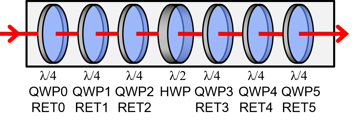
Schematic of EPS1000 polarization scrambler
 |
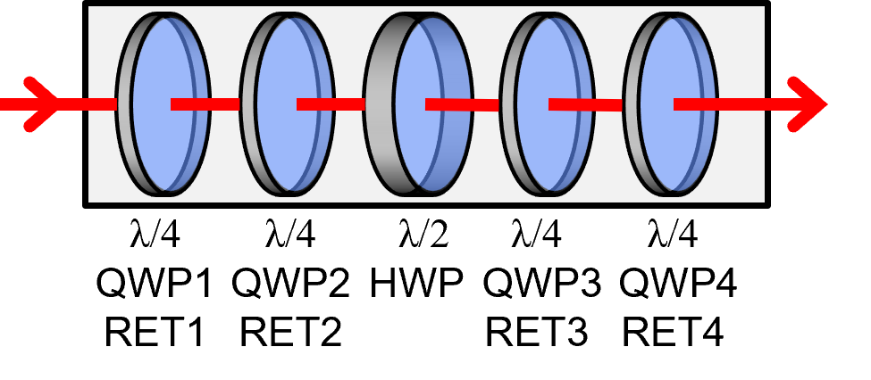
Waveplates in EPS1000-20M and EPS1000-10M |
 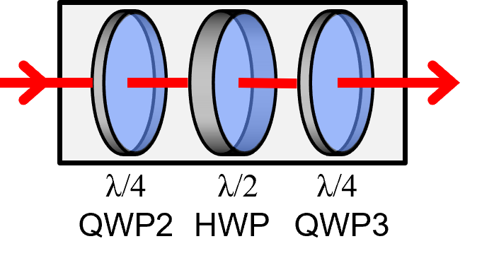 |
Waveplates in depolarizer-version of EPS1000-50M |
 |
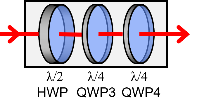
Waveplates in EPS1000-XXM (XX = 40, 60, 80; standard since 02/2026). Ideally suited for precise testing of coherent receivers at highest scrambling speeds, up to 80 Mrad/s. |
Electrooptic rotating quarterwave plates (QWP0...QWP5) and a halfwave plate (HWP) are traversed by the light. This way arbitrary input polarizations are scrambled. In all Poincaré sphere representations here below the HWP rotates fast compared to QWP1...QWP4, and QWP0, QWP5 are not implemented.
Rotating QWPs have time-variable orientation. When also retardation is time-variable a QWP becomes a linear retarder (RET). One can switch between QWP and RET operation. RET operation improves scrambling randomness. Therefore RET1, RET2, HWP, RET3, RET4 behave very similar to the established QWP0, QWP1, QWP2, HWP, QWP3, QWP4, QWP5. But with 5 rather than 7 waveplates, EPS1000-XXM (XX = 40, 60, 80) is a lot faster (HWP = 40, 60, 80 Mrad/s; QWPs = 3 Mrad/s) than the established EPS1000-20M (HWP = 20 Mrad/s, QWPs = 2 Mrad/s).
Function of waveplates in EPS1000 polarization scrambler
A polarization transformer made from LiNbO3 is configured such that it contains cascaded electrooptic waveplates. Each electrical period of waveplate voltages corresponds to half a mechanical turn of a waveplate. As the scrambling speed we define that speed on the Poincaré sphere which occurs if a waveplate generates rotating linear polarization.
QWP0 to QWP2 scramble the unknown input polarization.
Dependent on this, the fast HWP generates circles in parallel planes of the Poincaré sphere with radii between 0 and 1, having an arithmetic mean of π/4. In each period of the HWP voltages such circle is traversed twice. At radius 1, corresponding to rotating linear polarization on the Poincaré sphere equator, a trajectory of length 4π is thus generated in each electrical period. The polarization change speed of the HWP, adjustable from -10,000 to
QWP3 to QWP5 subsequently scramble the orientations of the circles and thereby distribute the polarization changes and their directions equally over the Poincaré sphere. A QWP can likewise generate rotating linear polarization, from circular input polarization. In doing so the Poincaré sphere equator is traversed once in each electric period of the QWP voltages, corresponding to a trajectory of length 2π. The polarization change speed of the QWPs, individually adjustable from -1,000,000 to
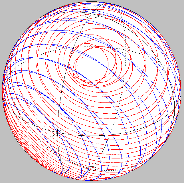
Poincaré sphere representations, recorded behind EPS1000 polarization scrambler
 |
 |
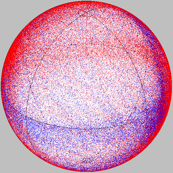 |
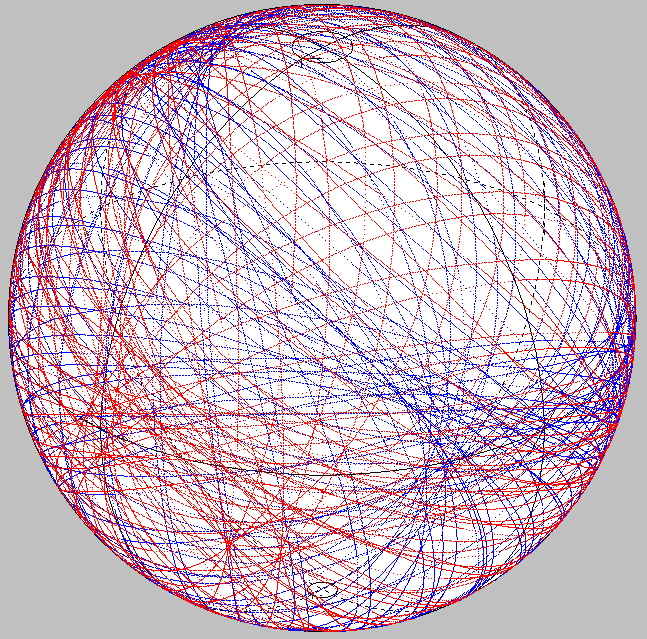
QWP0 and QWP5 are not implemented here. All other waveplates are running: QWP1, QWP2, HWP, QWP3, QWP4. Rightmost: HWP rotates fast. Everywhere else, also below: HWP rotates slowly. | |
 |
 |
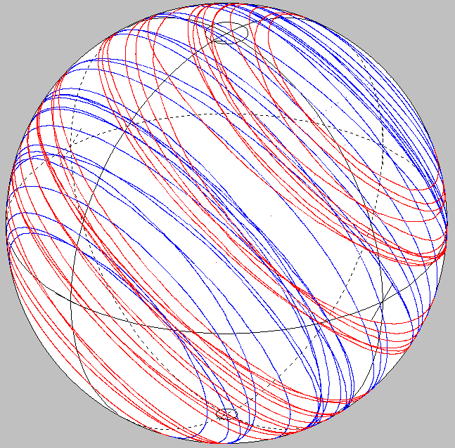
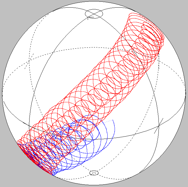
QWP1, QWP2 at the front transform the input polarization of the HWP which therefore generates circles of varying sizes in parallel planes. QWP3, QWP4 at the rear are switched off. | |
 |
 |
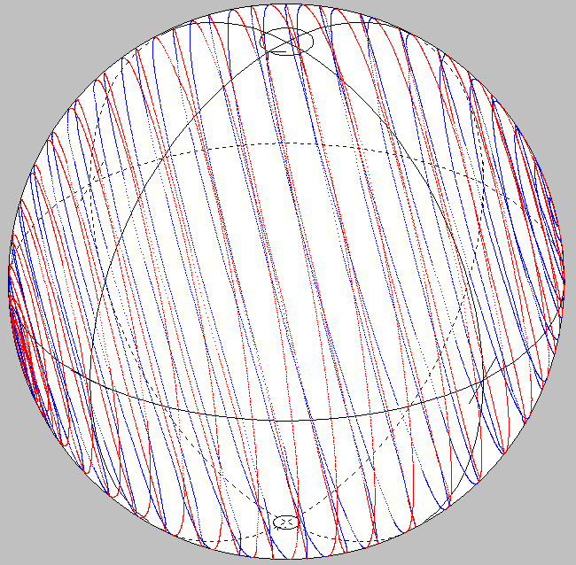
QWP1, QWP2 at the front are switched off. The HWP generates large (left) or small (right) circles. These are transformed by QWP3, QWP4 at the rear into varying orientations. |
Polarization scrambling at 80 Mrad/s
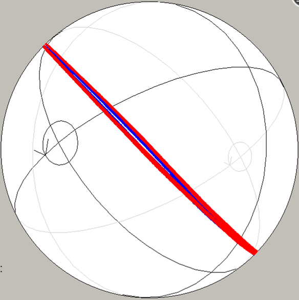 |
Halfwave plate witn locally linear polarization running at 80 Mrad/s in EPS1000-80M | |
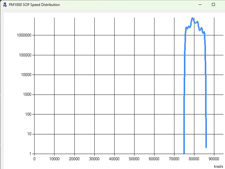 |
Semilogarithmic speed distribution generated by halfwave plate with locally linear polarization, running at 80 Mrad/s in EPS1000-80M | |
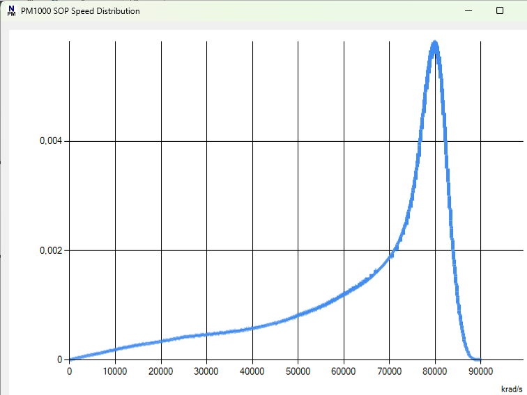 |
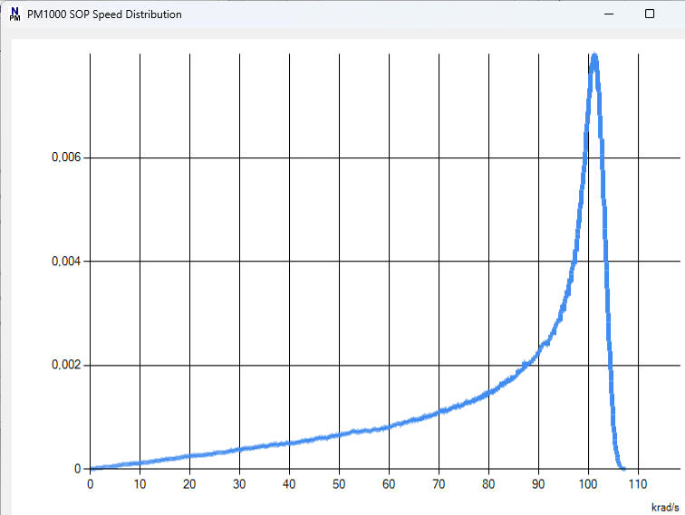
Peaked speed distribution 80 Mrad/s generated by RET1, RET2, HWP, RET3, RET4 in EPS1000-80M. Speed distribution is calibrated up to 80 Mrad/s. Peaked distribution is dominated by fast speeds. This allows fast testing of coherent receivers designed for a certain control speed. | |
 |
Similar to above, but 100 krad/s |
Step response of EPS1000-80M polarization scrambler
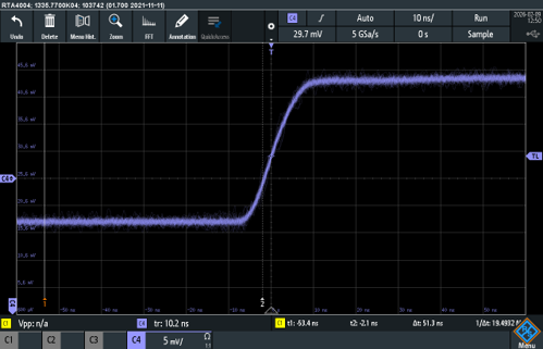 |
Electroptic step response 10 ns of EPS1000-80M, measured with photodiode behind polarizer. Horizontal: 10 ns/div. Vertical: not to scale. |
Polarization-dependent loss (PDL) measurement
For details see Section IV. here. PDL measurement requires an EPS1000 equipped with 1 or 2 optical power detectors. For various generated polaization states the optical power behind the device under test (DUT) is measured. The averaging interval is selectable (80 ns, 160 ns, 320 ns, ... 2.68 s). With default settings, one set of measurements plus data transfer takes about 30 s. Reference measurements allow the losses of the LiNbO3 polarization transformer inside the EPS1000 to be mathematically eliminated. Minimum, mean and maximum attenuation and PDL of the DUT are thus determined. Typical results follow.
| PDL reproducibility A fiber is used as the reference and as the DUT. |
< 0.003 dB |
| PDL values and error ranges 6 DUTs, which are 1 patchcord, 4 PDL components and 1 polarizer, are measured against a reference. This is repeated at least 10 times with different input polarizations of the EPS1000 and different polarization transformations before and behind the DUT. PDL value with error range is given for each DUT. The maximum perceived patchcord PDL (0.0276 dB) is a measure of the total error window of small PDL. |
0.0186±0.009 dB 0.0799±0.018 dB 0.433±0.041 dB 1.59±0.087 dB 7.33±0.051 dB 50.4±1.5 dB |